 Additive Realm
For PETG vs PLA for functional parts, choose by how the part will fail, not by which filament is ‘stronger’. Heat (a car, an enclosure, next to a motor): pick PETG. Cool, indoors and has to stay stiff: pick PLA. Full sun: don’t trust either untested.
In a lab UV-aging study, PETG lost far more tensile strength than PLA, but a lab UV exposure may not match outdoor sunlight. If you can’t tell which way your part will fail, the hang-and-heat test further down settles it in a week for a few grams of each filament.
PETG vs PLA for Functional Parts: Why ‘Stronger’ Is the Wrong Question
The usual advice is a spec table plus one line: PETG is stronger. In a controlled study of printed neat materials, it wasn’t: PLA reached 59.9 ± 2.9 MPa ultimate tensile strength against 54.9 ± 2.6 MPa for PETG, and PLA was also stiffer, with a Young’s modulus of 1102.3 ± 17.8 MPa vs 1008.3 ± 47.6 MPa.
So for a part pulled once, slowly, at room temperature, that study’s numbers favour PLA. Functional parts fail in four ways, though, and the research points in different directions on each. Sunlight isn’t on this list because it’s an exposure, not a failure mode: UV weakens the plastic over months, and I deal with it in the outdoor section.
The first is heat softening: the part goes floppy because it’s warm, with or without load. The second is creep, where a constant load slowly bends the part over days or weeks.
The third is impact, meaning one sharp hit, a drop or a slammed door. The fourth is repeated flex in clips, snap-fits and hinges that bend every time you use them. Name yours before you open the filament drawer.
Many parts face more than one failure mode: a car phone mount faces heat and vibration, and a shelf bracket faces creep and the occasional knock. When two modes point different ways, the one that would kill the part fastest decides.
The Numbers That Matter: Strength, Stiffness, Heat and UV Side by Side
These are the figures I compare. The first four rows come from the same printed-specimen study, so those comparisons are apples to apples. Its Tg row gives two numbers: the value from the paper’s reference table, then what the researchers measured on their own filaments by DSC. The UV row comes from a separate UV aging study.
| Property | PLA | PETG |
|---|---|---|
| Tensile strength | 59.9 ± 2.9 MPa | 54.9 ± 2.6 MPa |
| Young’s modulus | 1102.3 ± 17.8 MPa | 1008.3 ± 47.6 MPa |
| Elongation at break | 8.1 ± 0.6% | 7.4 ± 0.3% |
| Tg, tabulated / measured | ~60 °C / 55.2 °C | ~80 °C / 69.3 °C |
| Tensile strength lost after accelerated UV aging | 5.3% | 36% |
On elongation, the two printed materials broke at almost the same stretch, so this study doesn’t make either one the obviously ductile choice. The table has no heat deflection temperature (HDT) or impact-strength (Charpy or Izod) row, because none of the studies linked here measured them. For brittleness against ductility, the evidence in this article is the flex test in the impact and flex section.
Heat: Where PLA Softens, How Much Headroom PETG Adds, and Places That Get Hotter Than You Think
Look at the Tg row in the table above. Near the glass transition, stiffness and dimensional stability drop, and on both the tabulated and the measured figures PLA gets there first.
The catch is the second number in that row. When the researchers measured their own filaments, both came in below the tabulated values: PLA at 55.2 °C and PETG at 69.3 °C. That leaves PETG about 14 °C of real headroom, not the 20 °C the tabulated figures suggest. It’s worth having, but it doesn’t make PETG safe to bolt onto anything warm.
You also shouldn’t design a part to sit just under Tg. Stiffness starts falling before you reach that number, so I keep the part’s hottest moment at least 20 °C below the measured Tg. For the PETG in the printed-specimen study, that caps it at about 49 °C; for the PLA, about 35 °C. If your thermometer peak lands above that line, the material is wrong, not borderline.
These are the hot spots I’d treat as suspect until measured: a car dashboard or parcel shelf, where sun through the glass bakes whatever sits there; the inside of an enclosed printer, which stays warm as long as the bed runs (check your model in our 3D printer database if you’re not sure it’s enclosed); anything bolted next to stepper motors or a power supply; and a sunny windowsill. How hot each one gets depends on the car, the printer and your climate, so measure it. Leave a thermometer probe in the spot for a day, through its warmest hours, and compare the peak with the Tg row.
Constant Load: Creep, and Why a PLA Bracket Can Sag Weeks After It Passed Day One
Creep is slow deformation under a load that’s well below breaking strength, and both filaments do it. In 5-day tensile creep tests on printed specimens, PLA under 7.5 MPa and PETG under 8 MPa both kept stretching after loading, though most of the stretch came the moment the load went on. Those loads were 25% of the tensile strength the creep study measured on its own specimens, a different batch from the printed-specimen study in the table.
A bracket that survives a short static load test can still deform later under sustained load, so a day-one test doesn’t prove the part will hold. Since both materials creep, design for it: keep stress low with thicker sections, ribs and generous fillets.
That study doesn’t give PETG a clean win on creep either. In its bolted-plate test, M6 nuts were tightened to 5.07 N·m on 8 mm printed plates; after seven days, the untreated plates took 4.92 N·m to undo on PLA and 4.49 N·m on PETG. The PETG plates had relaxed more under the clamp, which matters for any bolted bracket.
Temperature is where the two separate. Stiffness and dimensional stability drop near the glass transition, and PLA’s sits about 14 °C lower on the measured figures, 20 °C on the tabulated ones (see the heat section). At the same warm room temperature, a PLA part is closer to that zone than a PETG one.
Impact and Flex: Designing and Testing Clips, Snap-Fits and Hinges in Either Filament
None of the studies I’m working from report impact figures for either filament, so I won’t tell you one snaps and the other bends. For clips, hinges and knock-prone parts, my verdict comes from the flex test further down: print both, flex both, keep the one whose root stays clean. Before you print, check elongation at break on each spool’s data sheet. The filament with the higher figure is the one I’d print first.
Stiffness is the one thing the data does settle. PETG’s lower modulus (see the table) means it deflects more under the same load. For a clip, that means a softer snap. For a positioning mount that must not move, stays indoors and never gets knocked, PLA’s extra stiffness works in your favour.
For clips and hinges, geometry matters more than filament, and the same rules hold for both. Put a generous fillet at the root of the arm, because that’s where strain piles up and cracks start. Taper the arm, thick at the root and thin at the tip, so the bend spreads along its length.
Print the clip with the arm flat on the bed so it flexes along its layers rather than across them, where every layer line is a ready-made crack.
Before committing, run a flex test, the clip’s version of the hang-and-heat test below. Print the clip in PLA and PETG with the same profile and orientation as the real part. Then flex each one to its working deflection a few hundred times, counting in batches of 50 to keep yourself honest.
Watch the root for whitening or hairline cracks, and check that the clip still springs back fully. The material that stays clean wins. If both whiten, fix the geometry before you swap filament.
Print Orientation: Why It Can Matter More Than the Filament
In tensile tests on PLA and PETG bars printed in nine orientations, the strongest orientation beat the weakest by 49% for PLA and 60% for PETG. The default, lying flat on the bed, was the weakest. Tilting the bar 45° so its perimeters ran along its length did best for both materials.
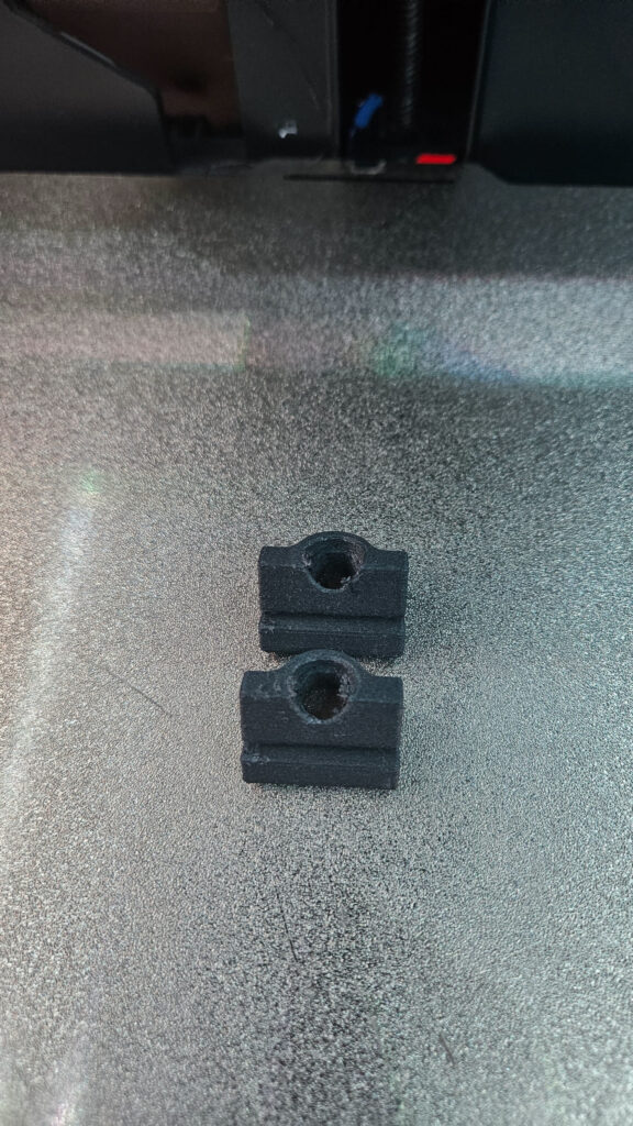
The tensile gap between the two materials in the table above is under 10%, so orientation can outweigh the filament choice. The rule holds for both: follow the load path, and orient the part deliberately for the load it carries instead of accepting the slicer default.
If your layers are splitting even with good orientation, check your print settings; my quick fixes for common print problems cover that. If a print service is making the part, state the orientation explicitly when you prepare the model, because their default may not match your load path.
A Simple Hang-and-Heat Test to Settle a Borderline Part Before You Commit
When a part is borderline, I’d rather spend a week of patience than guess. This test costs a few grams of each filament. Print the same simple cantilever beam in PLA and PETG with the same slicer profile, the same walls and the same orientation as the real part. Don’t skip matching orientation: the section above shows why it can outweigh the filament choice.
Clamp each beam flat to a shelf edge with most of its length sticking out. Hang a weight from the tip that matches the real load, then double it for margin. A filled water bottle makes a handy known weight. Tape a strip of paper to the wall behind the tip and mark its position right after loading.
Now move the rig to the warmest place the real part will live: a car on a sunny day, inside the printer enclosure, next to the radiator. Mark the tip again after an hour, a day and a week. Expect both beams to keep dropping a little, because both materials creep.
A beam passes if its total tip drop at one week stays within the deflection the real part can tolerate, and if the drop from day 1 to day 7 is clearly smaller than the drop from hour 1 to day 1, so the sag is slowing down. If both pass, the beam that sagged less wins.
If you can’t wait a week, there’s a rough shortcut that tests heat alone. Heat a pot of water to the hottest temperature your part will see, check it with a kitchen thermometer, and dunk the loaded beam for 30 minutes. A sag is a strong warning sign. This won’t reveal slow creep, so treat a pass as promising, not proven.
When the numbers say ‘maybe’, this test is the tie-breaker. Make the beam thickness a parameter in your CAD model so a second round takes one edit. My guide to parametric design in Fusion 360 shows how I set that up.
Pick by Part: Brackets, Mounts, Gears, Car Interior and Outdoor Use, Each With My Verdict
Indoor shelf and wall brackets: PLA is fine if the room stays at normal temperatures and you design for low stress. Its higher stiffness (1102.3 vs 1008.3 MPa) means less flex under the same load. Both materials creep, so oversize the section rather than trusting a day-one test. If the bracket sits above a radiator or in a garage that bakes in summer, switch to PETG.
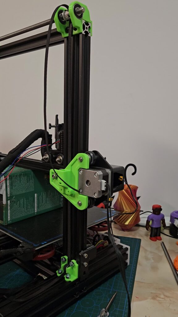
Mounts and electronics enclosures: PETG, almost by default, because electronics, motors and power supplies make heat, boxes trap it, and PETG’s glass transition is higher. The only case where I’d pick PLA here is a cool, passive mount that never gets knocked and has to hold position precisely.
Gears: a light-duty, cool, indoor gear train where precise meshing matters can run in PLA, because its higher modulus keeps teeth from deflecting. Test a gear that can stall or jam before trusting either filament.
Car interior: PETG, and only out of direct sun. PETG’s measured Tg of 69.3 °C isn’t a huge buffer: with the 20 °C margin from the heat section, the spot’s measured peak has to stay under about 49 °C. Log the peak with a thermometer probe, then run the hang-and-heat test in the car itself before trusting either filament.
Outdoor use is where the ‘PETG for everything’ advice deserves a second look. Check the UV row in the table: under that study’s accelerated UV aging, PETG lost far more tensile strength than PLA. That was 24 hours of UV-B in a lab chamber, which the authors equate to several months of sun, not real outdoor weathering, so read it as a warning about PETG in sun, not as proof that PLA survives outdoors.
For shaded outdoor parts under load, I’d still pick PETG. For load-bearing parts in full sun, I wouldn’t use either as-is. Print the part in a UV-resistant filament such as ASA, or paint or coat it so sunlight never reaches the plastic. ASA prints best in an enclosed printer; if yours is open-frame, our Compare 3D Printers page lets you line up enclosed models side by side.
| Failure mode | My pick | Caveat |
|---|---|---|
| Heat softening | PETG | Keep the hottest peak at least 20 °C below its measured Tg, about 49 °C for the 69.3 °C PETG here |
| Creep under constant load | Either | Both creep; oversize the section and run the hang-and-heat test |
| Impact and repeated flex | Flex test decides | No impact data in these studies; print the higher-elongation spool first, then confirm with the flex test |
| Stiffness in a cool room | PLA | Only if it never sees heat |
| Full sun | Neither as-is | The only UV data here is a lab aging study, not outdoor weathering; use ASA, or paint or coat the part |
Sources
- 3D Printing and Additive Manufacturing (Mary Ann Liebert), via PubMed Central: The Mechanical Properties of 3D-Printed PLA/PETG Multi-Material Structures Manufactured by Material Extrusion
- Polymers (MDPI), via PubMed Central: Aging of 3D Printed Polymers under Sterilizing UV-C Radiation
- MM Science Journal: Influence of Layer and Fibre Orientation on Tensile Strength of PLA and PETG Samples
- Polymers (MDPI), via PubMed Central: Accelerated Aging Effect on Mechanical Properties of Common 3D-Printing Polymers